PLC vs DCS vs SCADA –
Key Differences Explained
A deep-dive into three foundational control technologies — their architecture, capabilities, trade-offs, and exactly when to deploy each one in real industrial environments.
Programmable Logic Controller — real-time, deterministic machine-level control for discrete and sequential processes.
Distributed Control System — integrated plant-wide continuous process control with built-in operator interface and historian.
Supervisory Control and Data Acquisition — enterprise-wide supervisory monitoring over geographically distributed field assets.
What Is a PLC?
A Programmable Logic Controller is a ruggedized, solid-state industrial computer purpose-built for deterministic real-time control of electromechanical processes. First commercialized in 1969 by Dick Morley to replace hardwired relay panels on automotive assembly lines, the PLC has since become the most widely deployed controller in industrial automation history.
The defining characteristic of a PLC is its scan cycle — a fixed, repeating loop in which the CPU reads all input states, executes the control program from top to bottom, and writes all output states. This cycle completes in 1 to 10 milliseconds, enabling the microsecond-level response times that high-speed machinery demands.
PLC Hardware Architecture
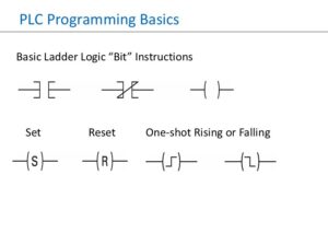
- CPU Module — executes IEC 61131-3 programs (Ladder Diagram, Structured Text, FBD, SFC, IL); manages memory, I/O bus, and scan timing
- I/O Modules — discrete I/O (24VDC, 120VAC), analog I/O (4–20 mA, 0–10V), specialty modules (encoder, thermocouple, high-speed counter, servo drive)
- Power Supply — 24VDC or 120/240VAC input; redundant PSU in critical applications
- Communications — EtherNet/IP, PROFINET, Modbus RTU/TCP, DeviceNet, PROFIBUS DP
- Backplane / Rack — high-speed local bus interconnecting all modules
Where PLCs Excel
PLCs are optimized for discrete, event-driven, and sequential logic — conveyor systems, robotic welding cells, injection molding machines, packaging lines, and motor control centers. Their low cost-per-I/O-point and wide vendor ecosystem (Allen-Bradley, Siemens, Mitsubishi, Omron, Schneider) make them the default choice for machine-level automation.
They are not, by design, plant-wide integration platforms. Historian functionality, advanced alarming, operator graphics, and multi-unit coordination require either a SCADA overlay or a DCS replacement.
What Is a DCS?
A Distributed Control System is an integrated control, supervision, and data management platform designed specifically for continuous process industries. Unlike a PLC, which is a standalone controller networked after the fact, a DCS is engineered from the ground up as a unified system — control, operator interface, historian, alarm management, and advanced process control all delivered by a single vendor architecture.
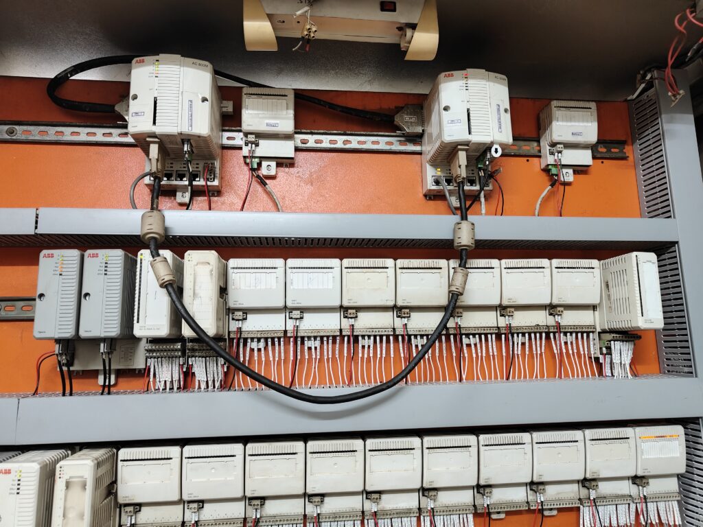
The word distributed refers to the physical distribution of control intelligence across multiple field controllers — called Field Control Stations (FCS) or Process Control Units (PCU) — each responsible for a defined section of the process. These controllers communicate over deterministic control networks (Foundation Fieldbus, PROFIBUS DP, or vendor-proprietary backbones) and present a unified process view to operators through ergonomically designed workstations.
DCS Three-Tier Architecture
- Field Level — Smart transmitters (HART, WirelessHART), control valves, analyzers connected via 4–20 mA, Foundation Fieldbus H1, or PROFIBUS PA
- Control Level — Distributed FCS/PCU controllers running PID, cascade, ratio, feedforward, and MPC at 100–500 ms scan intervals; fully redundant CPU and I/O
- Supervisory Level — Operator workstations (OWS), engineering workstations (EWS), integrated historian, ISA 18.2-compliant alarm management, and batch management servers on a Plant Control Network (PCN)
DCS and Functional Safety
Leading DCS platforms — Honeywell Experion PKS, ABB System 800xA, Emerson DeltaV, Yokogawa CENTUM VP, and Siemens PCS 7 — natively support SIL 2 and SIL 3 safety instrumented functions (SIF) per IEC 61511, with hot-swap I/O modules, redundant control paths, and integrated Safety Instrumented System (SIS) functionality. This level of fault tolerance is what justifies the premium cost in refineries, chemical plants, and power generation facilities where unplanned shutdowns cost tens of thousands of dollars per hour.
What Is SCADA?
Supervisory Control and Data Acquisition is a software framework — not a field controller. This is the most misunderstood fact about SCADA. It does not close control loops in real time. Control still executes in the PLCs, RTUs, or IEDs at the field level. SCADA sits above them, collecting data, presenting a unified operator interface, and sending high-level set-point commands back to field devices.
SCADA’s defining capability is geographic reach. A SCADA system can aggregate data from hundreds of field sites spread across thousands of kilometers — something neither a PLC nor a DCS is designed to do. Communication media include fiber optic, cellular (4G/5G LTE), licensed radio, MPLS, satellite (VSAT), and public internet (with VPN/encryption). Protocols include DNP3, IEC 60870-5-101/104, Modbus TCP, OPC-UA, and IEC 61850 for power utilities.
SCADA System Components
- Field Devices — PLCs, RTUs (Remote Terminal Units), IEDs, smart meters performing local control and reporting
- Communication Infrastructure — multi-media WAN connecting all field sites to the central SCADA server
- Master Terminal Unit (MTU) / SCADA Server — polls field devices, applies data quality codes, manages alarming, distributes to clients; often redundant or virtualized
- Historian — time-series database storing values at 1-second (or faster) resolution; AVEVA PI, AspenTech IP.21, Ignition Tag Historian
- HMI / Operator Console — graphical process displays, alarm management, trending, and report generation; Wonderware (AVEVA), Ignition, WinCC, GE iFIX, Schneider EcoStruxure
SCADA vs HMI — An Important Distinction
An HMI is a local operator terminal, typically machine-mounted or panel-mounted. SCADA is a plant- or enterprise-wide supervisory system incorporating multiple HMI nodes, servers, historians, and alarm aggregators. Every SCADA system includes HMI capability, but a standalone HMI is not a SCADA system.
Comprehensive Comparison Table
| Parameter | PLC | DCS | SCADA |
|---|---|---|---|
| Primary Function | Discrete & sequential machine control | Continuous process control | Supervisory monitoring & data acquisition |
| Control Type | Real-time deterministic I/O | Continuous PID, cascade, MPC | High-level set-point commands to field devices |
| Scan / Update Rate | 1–10 ms | 100–500 ms | Seconds to minutes (polling) |
| Geographic Scope | Single machine or cell | Single plant or process unit | Multi-site, regional, enterprise-wide |
| I/O Count | Tens to a few thousand | Thousands to tens of thousands | Virtually unlimited (via field controllers) |
| System Integration | Modular; integrated post-sale | Fully integrated, single vendor | Software over heterogeneous field devices |
| Native Redundancy | Optional; requires engineering | CPU, I/O, and network redundancy standard | Server-level; field redundancy in PLCs/RTUs |
| HMI / Visualization | Requires separate package | Built-in operator workstations | Core function of the system |
| Historian | Not native; third-party | Integrated | Integrated |
| Programming Standard | IEC 61131-3 (LD, FBD, ST, SFC, IL) | Vendor-specific + IEC 61131-3 | Configuration-based; no IEC 61131-3 |
| Key Protocols | EtherNet/IP, PROFIBUS, Modbus | Foundation Fieldbus, HART, PROFIBUS PA | DNP3, IEC 60870, OPC-UA, Modbus TCP |
| Functional Safety | SIL 1–2 (separate SIS required) | SIL 2–3 natively with integrated SIS | Not a safety system |
| Typical Application | Conveyors, packaging, motor control | Refinery, chemical plant, power plant | Pipelines, water networks, power grid |
| Key Vendors | Allen-Bradley, Siemens, Mitsubishi, Omron | Honeywell, ABB, Emerson, Yokogawa | Wonderware, Ignition, WinCC, GE iFIX |
| Cost Model | Low per-unit; low integration cost | High upfront; lower lifecycle cost | Software licensing + server infrastructure |
How All Three Fit: The Purdue Reference Model
PLC, DCS, and SCADA are not competing alternatives — in large facilities they coexist as distinct layers of the ISA-95 / Purdue Reference Model control hierarchy:
Industrial Use Cases in Depth
Automotive Assembly Line — PLC
A body-in-white (BIW) robotic welding line is the textbook PLC application. Each robot cell spot-welds specific points in a defined sequence, conveyors index body panels, and vision systems verify weld quality — all discrete, sequential operations. Dedicated Allen-Bradley ControlLogix or Siemens S7-1500 PLCs control each cell with 50–100 ms cycle times. A line SCADA/HMI aggregates OEE metrics and fault data. A DCS here would be architecturally mismatched and unnecessarily expensive.
Crude Oil Distillation Unit — DCS
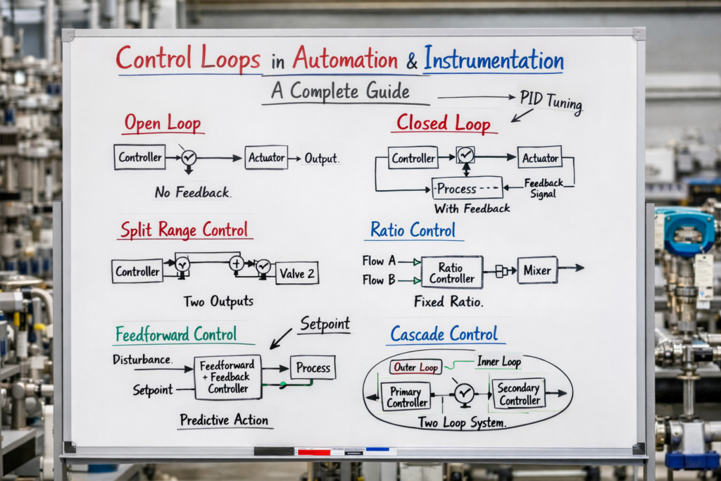
A crude distillation unit (CDU) operates continuously with tightly coupled variables: feed rate, furnace outlet temperature, tower pressures, draw temperatures, and product cut points. A change in any one cascades through the entire unit. Honeywell Experion PKS or Emerson DeltaV manages thousands of PID, cascade, and ratio control loops with Model Predictive Control (MPC) overlaid to maximize throughput and minimize fuel consumption. Integrated alarm management per ISA 18.2 and a native historian complete the picture. A standalone PLC architecture could not practically deliver this level of integration.
Natural Gas Transmission Pipeline — SCADA
A 2,000 km natural gas transmission pipeline has compressor stations, metering stations, and block valve sites at 50–100 km intervals. Each site has a local PLC/RTU managing compressor control and emergency shutdown. Operators in a central control room hundreds of kilometers away use a SCADA system — communicating via DNP3 over MPLS and cellular — polling all remote sites every 10–30 seconds. Operators command valve positions and compressor set-points from a geographic display. Local PLCs/RTUs operate autonomously if SCADA communication is lost, a principle called autonomous fallback mode.
Municipal Water Treatment — Hybrid PLC + SCADA
A city water system typically combines both technologies. A local PLC rack at the treatment plant manages dosing pumps, filtration, and UV disinfection. Simultaneously, a SCADA system oversees the entire distribution network — booster pump stations, storage tanks, pressure zones, and remote metering — spread across the entire municipality. Hydraulic model set-points, main-break alerts, and pump-failure alarms are all managed centrally. Increasingly, AMI (Advanced Metering Infrastructure) data feeds demand forecasting directly into pumping schedule optimization.
Gas Turbine Power Plant — All Three Layered
A combined-cycle (GTCC) power plant demonstrates the full layered architecture. The OEM-supplied turbine control system (GE Mark VIe or Siemens T3000) — essentially an advanced PLC — handles fuel control, ignition sequencing, and overspeed protection at 10 ms scan rates. Balance-of-plant systems (cooling water, steam bypass, auxiliary boilers) are managed by an ABB or Emerson DCS. At the top, an energy management SCADA system interfaces with the regional grid operator via IEC 61850 and ICCP (TASE.2), enabling Automatic Generation Control (AGC) to raise or lower megawatt output in response to grid frequency deviations.
Cybersecurity Considerations
As industrial control systems become more connected — OT/IT convergence, cloud historian integration, remote monitoring — cybersecurity has become a critical engineering discipline, not an afterthought.
- PLCs — historically air-gapped; now exposed via EtherNet/IP and remote access. Stuxnet demonstrated that even air-gapped PLCs can be compromised via removable media. Apply defense-in-depth: network segmentation, firmware integrity verification, and disable unused communication ports.
- DCS — vendors now ship security-hardened configurations per ISA/IEC 62443. The control network (PCN) must be isolated from the corporate network via a properly configured DMZ with unidirectional security gateways (data diodes) where possible.
- SCADA — the highest-priority attack surface due to its wide geographic footprint and diverse communication media. NERC CIP (for power utilities) and IEC 62443 mandates govern security controls including encrypted communications, multi-factor authentication, and vulnerability patch management programs.
Choosing the Right System: A Practical Decision Guide
The right control architecture depends on your process type, scale, integration requirements, and budget. Use this framework as a starting point:
Choose PLC When…
- Process is discrete or sequential
- Response time < 10 ms is required
- Per-machine cost is a primary driver
- Standalone or cell-level automation
- Maintenance staff prefer relay-style logic
Choose DCS When…
- Continuous process with tightly coupled variables
- Thousands of I/O points in one facility
- Integrated alarm, historian, and APC needed
- SIL 2/3 functional safety required
- 24/7 uptime with zero-downtime maintenance
Choose SCADA When…
- Assets are geographically dispersed
- Remote monitoring over WAN is needed
- Field controllers already exist (PLCs/RTUs)
- Enterprise-wide visibility is the goal
- Regulatory data logging is required
Conclusion
PLC, DCS, and SCADA are not interchangeable labels for the same technology — they represent three distinct engineering philosophies addressing three distinct problem spaces. The PLC delivers fast, deterministic, cost-effective machine-level control. The DCS provides deeply integrated, resilient, and intelligent process control for continuous operations. SCADA extends situational awareness and supervisory capability across geographic distances that neither PLC nor DCS can span alone.
In practice, the most sophisticated industrial installations — refineries, power plants, water utilities, and pipeline networks — deploy all three in concert, layered according to the Purdue model. The engineer’s task is not to pick one and dismiss the others, but to understand where each layer begins and ends, and to design the interfaces between them with the same rigor applied to the control logic itself.
Mastering this distinction is what separates a systems thinker from someone who merely configures controllers.