Control Valve Datasheet Explained – Complete Guide for Engineers
Control valves are one of the most important components used in industrial automation systems. They regulate process variables such as flow, pressure, temperature, and level.
However many engineers struggle to understand the information provided in a control valve datasheet. A typical datasheet contains many parameters including Cv, valve trim design, actuator configuration, pressure rating, and leakage class.
In this guide we will explain how to read a real industrial control valve specification sheet and understand the important parameters engineers must consider during valve selection.
Why Control Valve Datasheets Are Important
A control valve is not selected based only on pipe size. Engineers must evaluate multiple process parameters before finalizing the valve design.
- Fluid properties
- Pressure conditions
- Operating temperature
- Required flow capacity
- Valve trim design
- Actuator type
- Fail-safe configuration
Understanding these parameters ensures reliable operation of the valve and stable process control.
1. Service Conditions in Control Valve Datasheet
Fluid Type
The fluid handled in this valve application is hot water in liquid form.
The type of fluid determines the material selection for the valve body and trim components.
Operating Temperature
The operating temperature is between 70°C to 75°C.
Temperature is important because it determines the selection of valve packing and sealing materials.
Design Pressure and Temperature
- Design Pressure: 10 kg/cm²
- Design Temperature: 90°C
These values represent the maximum safe limits that the valve can handle.
2. Line Size and Piping Details
Pipeline Size
The pipeline size specified is 5 inch (125 mm).
Although the pipe size is 5 inches, control valves are selected based on flow coefficient (Cv) rather than pipe diameter alone.
Pipe Schedule
The pipeline schedule used is Schedule 40.
Pipe schedule indicates the wall thickness of the pipe and determines its pressure handling capability.
3. Control Valve Body Specifications
Valve Type
The datasheet specifies a Globe 2-Way Control Valve.
Globe valves are widely used in process control applications because they provide excellent throttling characteristics and accurate flow control.
4. Flow Coefficient (Cv)
One of the most important parameters in any control valve datasheet is the flow coefficient.
The Cv value represents the flow capacity of the valve. It indicates how much water can pass through the valve with a pressure drop of 1 psi.
Correct Cv selection ensures stable flow control and prevents valve oversizing.
Download the Original Control Valve Datasheet
You can download the same industrial control valve specification sheet used in this explanation.
Download Control Valve Datasheet5. Valve Trim Design
Balanced Ported Trim
Balanced trim reduces the force required to move the valve plug and improves valve performance at higher pressure drops.
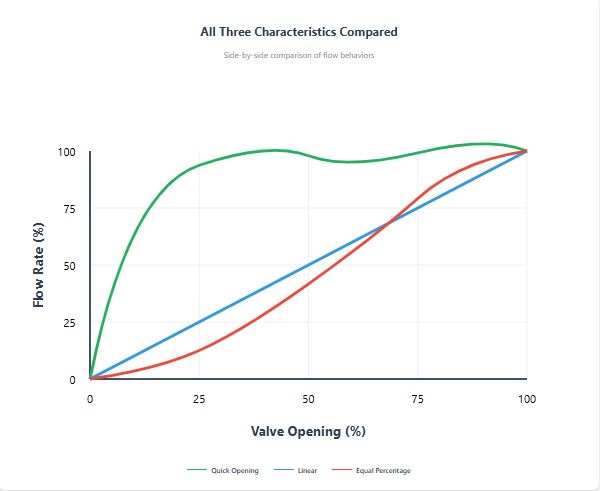
Equal Percentage Flow Characteristic
The valve uses an equal percentage characteristic which is commonly used in industrial processes.
This characteristic provides stable control across a wide range of operating conditions.
6. Leakage Class
The leakage class specified is Class IV according to FCI 70-2 standard.
| Leakage Class | Description |
|---|---|
| Class II | General service valves |
| Class IV | Tight industrial shutoff |
| Class VI | Bubble tight shutoff |
7. Valve Body Material
The body and bonnet material used is ASTM A216 WCC carbon steel.
This material provides high mechanical strength and good resistance to moderate temperature conditions.
The trim material used is SS304 which provides corrosion resistance and long service life.
8. Control Valve Actuator
The valve uses a diaphragm single spring actuator.
This actuator type is widely used in process industries because it is simple, reliable, and requires minimal maintenance.
Spring Range
0.8 – 1.6 kg/cm²
Fail Safe Position
The valve is configured as Air to Open (Fail Close).
This means if instrument air fails, the valve automatically closes to protect the process.
9. Control Valve Positioner
The valve is equipped with an electro-pneumatic positioner which converts electrical signals to pneumatic pressure signals.
Control signal conversion:
This ensures accurate valve positioning and stable control performance.
Download the Control Valve Datasheet
Click the button below to download the full control valve specification sheet used in this article.
Download Datasheet PDFFinal Thoughts
Understanding control valve datasheets is a critical skill for instrumentation and control engineers.
Each parameter in the datasheet plays a role in ensuring reliable valve performance, safe plant operation, and accurate process control.
Engineers who properly understand these specifications can avoid common mistakes such as valve oversizing, cavitation problems, and unstable control loops.