
How Industrial Signal Cables Protect 4-20 mA Signals
In industrial automation systems, instrumentation cables are the lifeline between field instruments and control systems.
These cables carry critical low-level signals such as 4-20 mA, which are used by systems like PLC and DCS to monitor and control industrial processes.However, industrial environments are full of challenges such as electrical noise, vibration, mechanical stress, and environmental damage.
To overcome these problems, instrumentation cables are designed with multiple protective layers, each serving a specific engineering purpose.
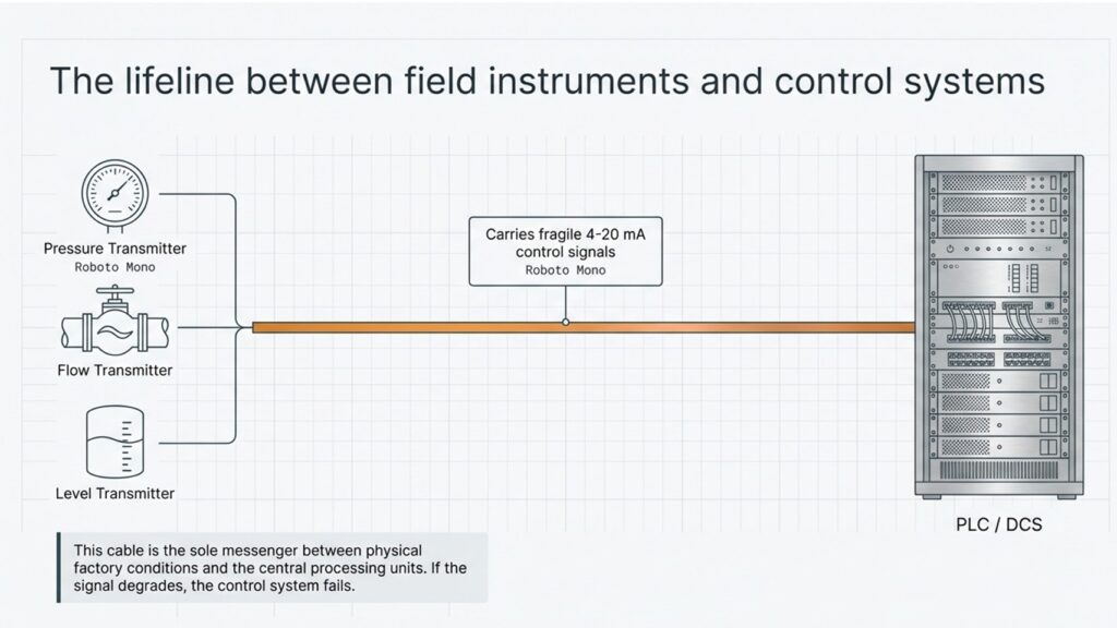
The Lifeline Between Field Instruments and Control Systems
Field instruments such as:
- Pressure Transmitters
- Flow Transmitters
- Level Transmitters
send their measurement signals to the control system using 4-20 mA current signals.
These signals travel through instrumentation cables and reach systems like:
- PLC (Programmable Logic Controller)
- DCS (Distributed Control System)
If the signal quality degrades due to interference or damage, the control system may receive incorrect information, which can affect the entire plant operation.
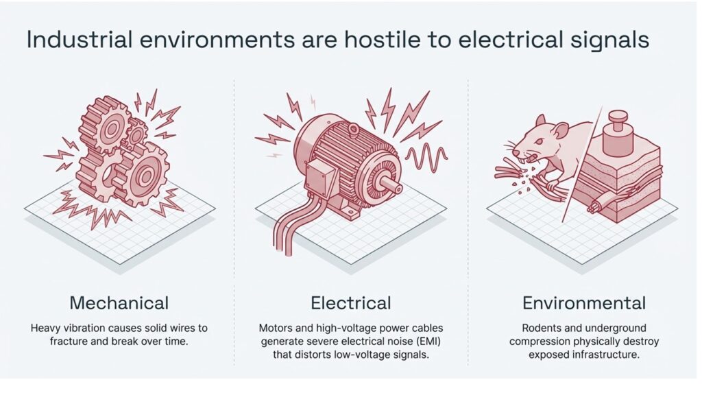
Industrial Environments Are Hostile to Electrical Signals
Industrial plants are not friendly environments for signal cables. Several factors can damage or distort signals.
1 Mechanical Stress
Heavy vibration from rotating equipment can cause solid conductors to crack or break over time.
2 Electrical Interference
Motors, power cables, and high-voltage equipment generate electromagnetic interference (EMI) that can distort sensitive signals.
3 Environmental Damage
Rodents, compression, and harsh environmental conditions can physically destroy exposed cables.
Because of these challenges, instrumentation cables are carefully engineered with multiple protective layers.
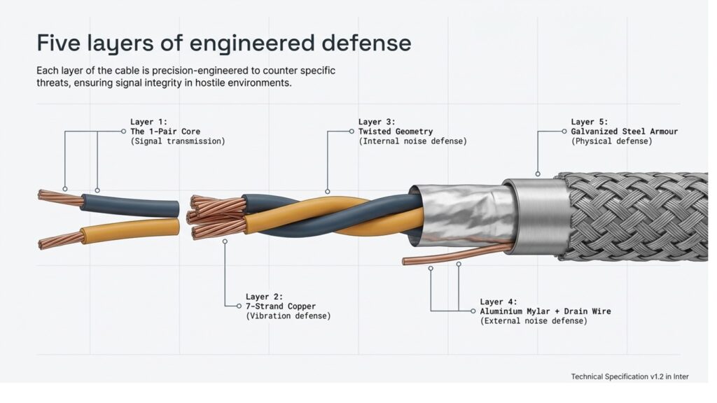
Five Layers of Engineered Defense in Instrumentation Cable
A 1-pair instrumentation cable is not just a simple wire. It is designed with multiple layers of protection, each solving a specific industrial problem.
Layer 1 – The 1-Pair Core
The basic structure consists of two conductors forming a single electrical loop.
These two wires transmit the 4-20 mA signal between transmitter and controller.
Layer 2 – 7-Strand Copper Conductor
Instead of a single solid wire, the conductor uses seven small copper strands.
This provides:
- Higher flexibility
- Better resistance to vibration
- Reduced chances of conductor fracture
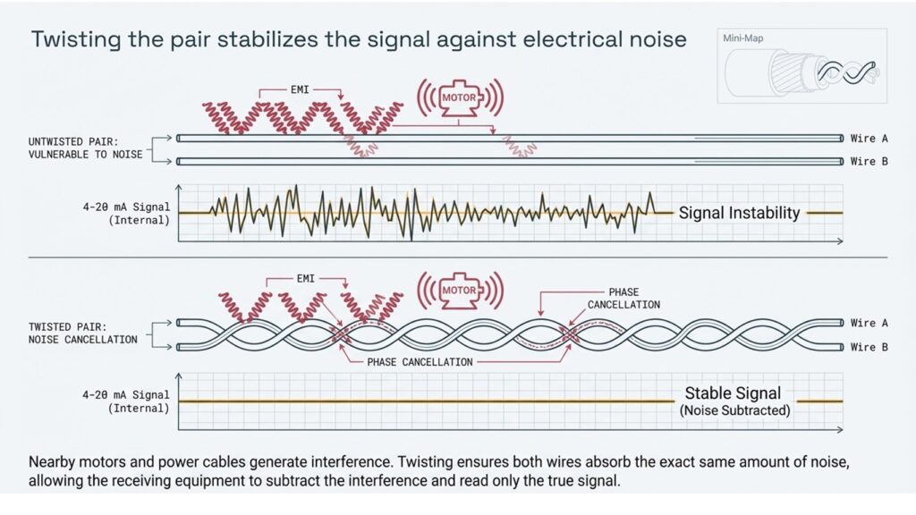
Layer 3 – Twisted Pair Geometry
The two wires are twisted together to reduce electromagnetic interference.
Twisting ensures that both wires experience the same external noise, allowing the receiving equipment to cancel it.
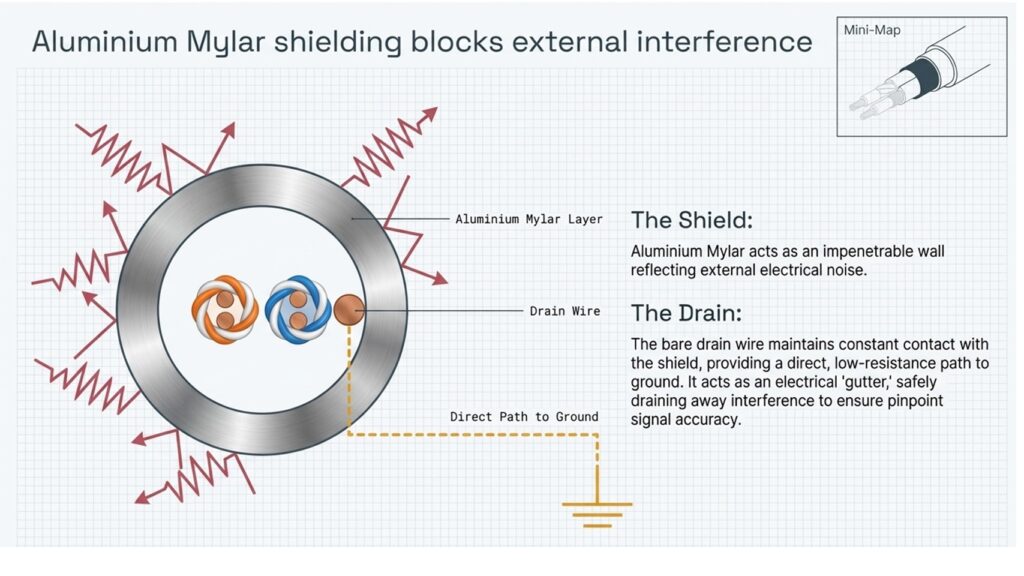
Layer 4 – Aluminium Mylar Shield + Drain Wire
A metallic shield surrounds the conductors to block external electrical noise.
The drain wire provides a direct path to ground, safely removing interference.
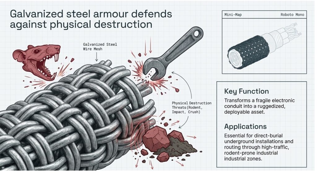
Layer 5 – Galvanized Steel Armour
An additional layer of steel armour protects the cable from:
- Mechanical damage
- Crushing forces
- Rodent attacks
Why a 1-Pair Cable Uses Two Conductors
Instrumentation systems typically use a single closed electrical loop.
In this loop:
- One wire carries the signal from transmitter to controller
- The second wire completes the return path
This creates a continuous signal loop that allows accurate measurement transmission.
Insert Image – Slide showing loop from transmitter to PLC
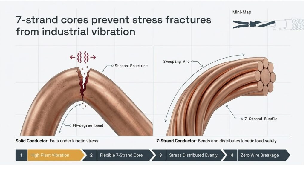
Why 7-Strand Conductors Are Used
A very common question in cable design is:
Why use 7 strands instead of a solid conductor?
The reason is mechanical durability.
Solid conductors tend to break when exposed to constant vibration and bending.
A 7-strand conductor distributes stress across multiple wires, allowing it to bend without fracturing.
Advantages include:
- Better flexibility
- Longer cable life
- Reduced failure in high vibration environments
How Twisted Pair Reduces Electrical Noise
Industrial plants contain many sources of electromagnetic interference, such as:
- Electric motors
- Variable frequency drives
- High-power cables
When the two conductors are twisted together:
- Both wires pick up the same external noise
- The receiving device cancels the noise using phase cancellation
This ensures that the true signal remains stable and accurate.
How Mylar Shielding Blocks External Interference
Instrumentation cables often include Aluminium Mylar shielding.
This layer acts as a protective barrier that reflects external electromagnetic noise.
The shield works together with the drain wire, which provides a direct grounding path for unwanted electrical energy.
Benefits of shielding include:
- Improved signal accuracy
- Reduced interference
- Stable transmission of low-level signals
Steel Armour Protects Against Physical Damage
In harsh industrial environments, cables are exposed to many physical threats.
These include:
- Rodent attacks
- Mechanical impact
- Underground stress
- Heavy equipment traffic
To prevent such damage, many instrumentation cables include galvanized steel wire armour.
This armour converts the cable from a fragile conductor into a rugged industrial-grade communication path.
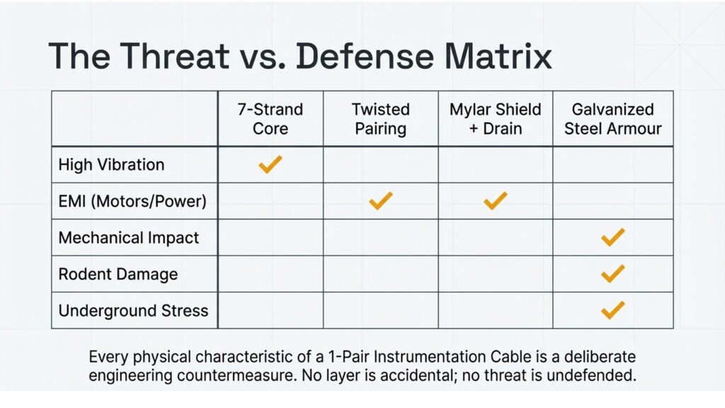
Threat vs Defense in Instrumentation Cable Design
Each component of the cable is designed to counter a specific threat.
| Industrial Threat | Cable Feature |
|---|---|
| High vibration | 7-strand conductor |
| Electrical interference | Twisted pair |
| External EMI | Mylar shielding + drain |
| Mechanical damage | Steel armour |
This layered design ensures high reliability of instrumentation signals in industrial plants.
Conclusion
A 1-pair instrumentation cable may look simple from the outside, but internally it contains a carefully engineered structure designed to protect delicate signals.
Each layer serves a purpose:
- Stranded conductors resist vibration
- Twisted pairs cancel electrical noise
- Shielding blocks interference
- Steel armour protects against physical damage
Together, these features ensure that critical 4-20 mA signals travel safely from field instruments to the control system, maintaining accurate monitoring and control of industrial processes.